Welcome to the home of NoPunIn10Did LLC, a sole proprietorship owned and operated by W. Alex Ronke. This site serves a dual role: first as the home of my commercial keyboard-related product design projects, and second as a permanent home for the Diplomacy variants that I create and run.
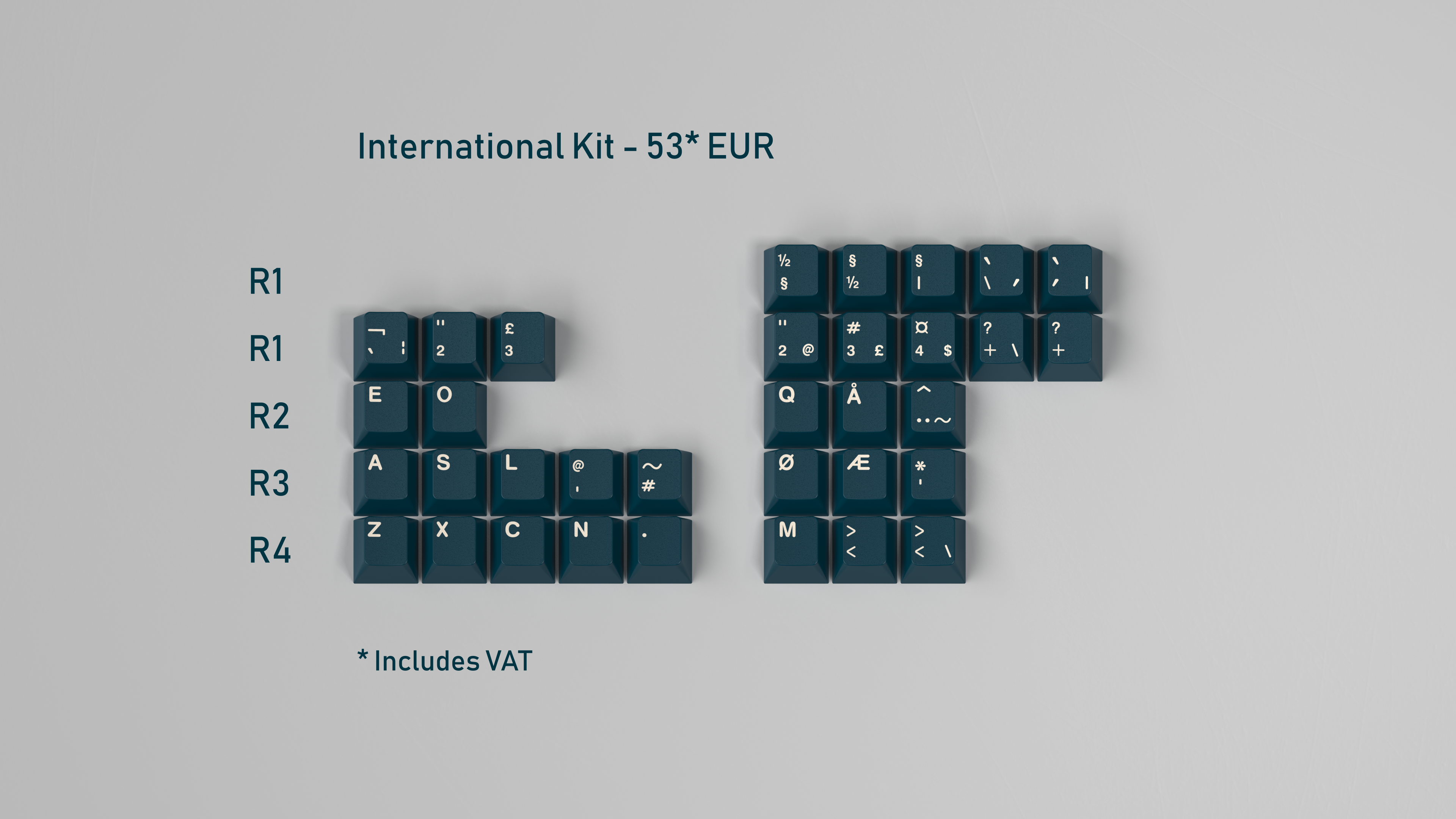
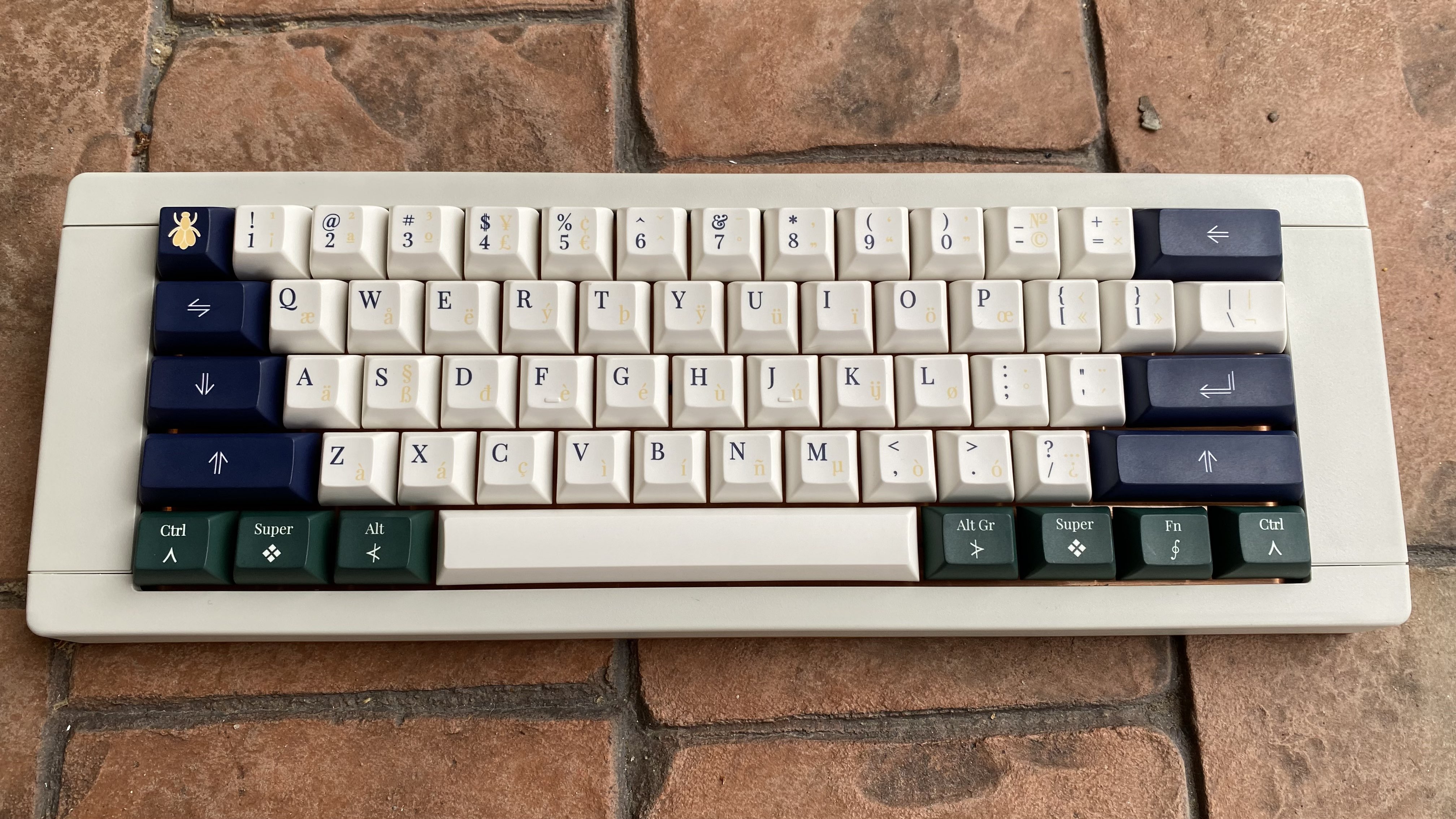
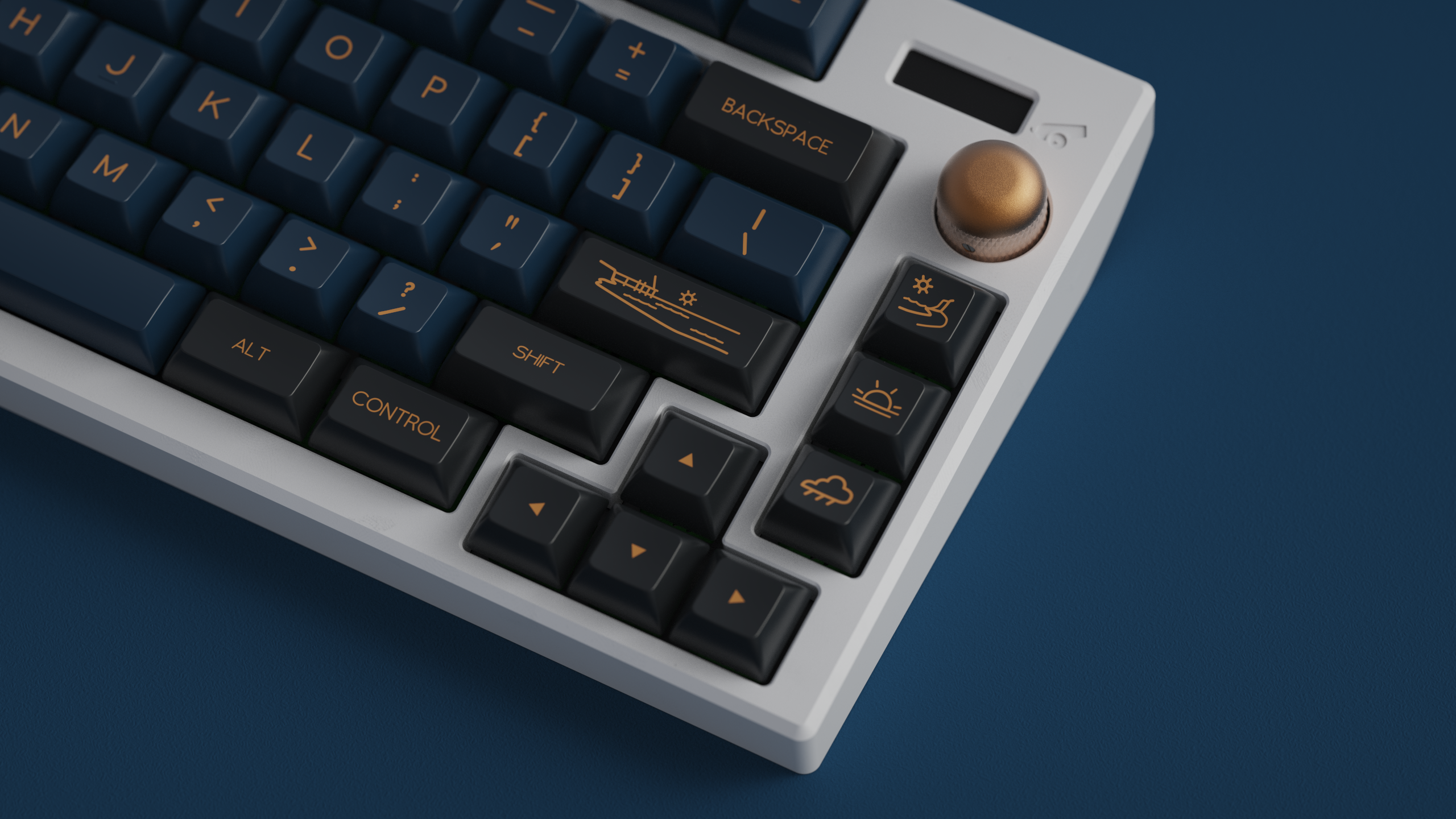
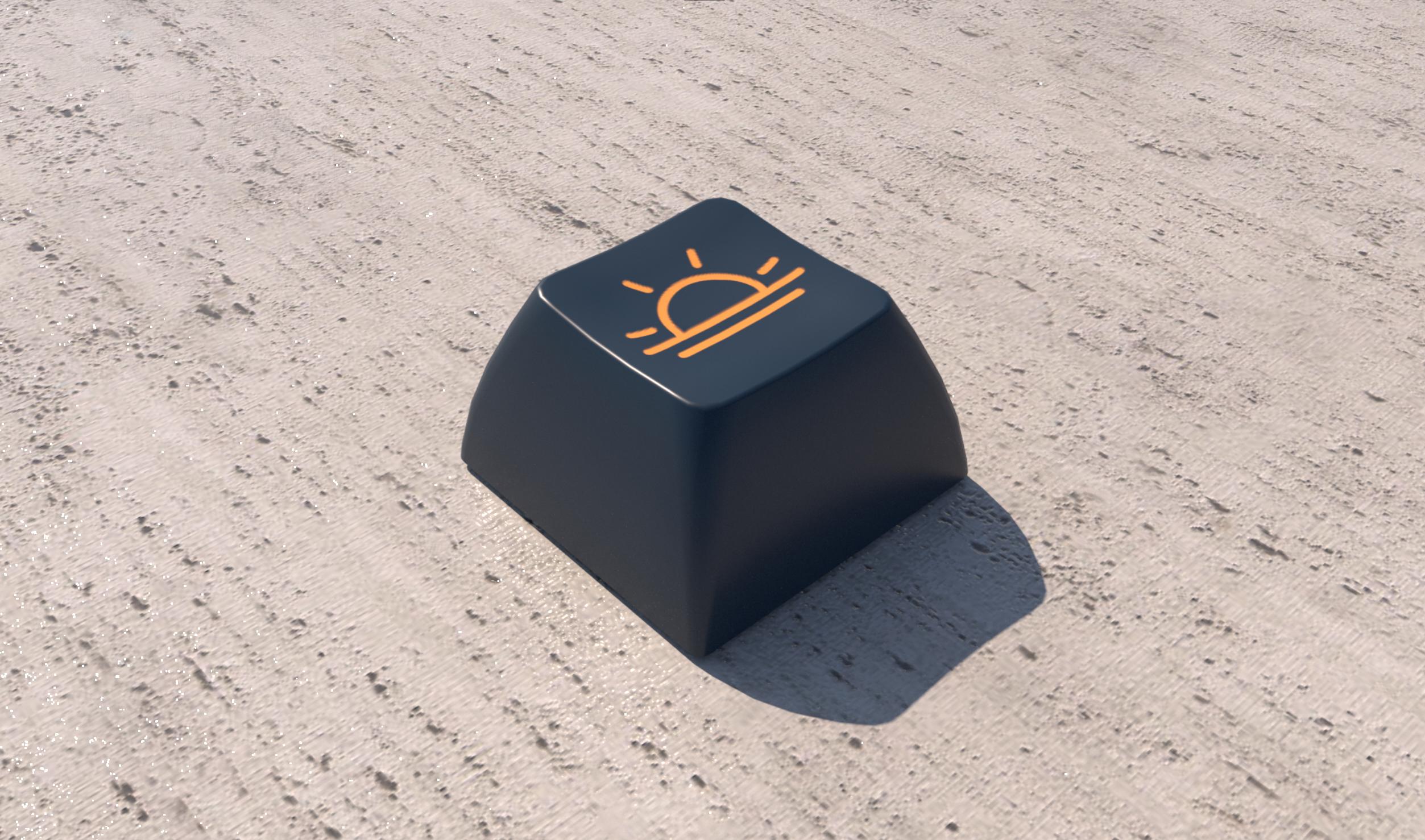
GMK CYL Prussian Blue!
Check out GMK CYL Prussian Blue is available worldwide for Group Buy preorder from March 21 through April 20!
Online Diplomacy Tournament!
In 2024, I ran a Diplomacy tournament via Discord: The 2024 Tournament Through Time. It consisted of three rounds of 2-3 tables each, 10 players per table, and a final “top table” round to determine the overall tournament winner. Check it out!
More Keyboards
While I have long had some interest in keyboards and input device technology, this interest crystallized into a devoted hobby circa 2018. It was at that point that I fell down the mechanical keyboard rabbit hole and discovered an avenue of technology that was simultaneously accessible, useful, creative, and customizable. I began purchasing and customizing my own keyboards, starting with running keycap “group buys” (a form of preorder) and eventually moving to selling my own keyboard PCBs and designs.
While this is not a traditional e-commerce site, projects for which I am the vendor (like the Jabberwocky) also include an order form (with the transactions themselves handled via Paypal invoice or similar).
As part of my keyboard work, I have been a contributor to the QMK open source Github repository as well as the public release of two of my experimental keyboards: the Railroad and Kastenwagen.
More Diplomacy
Additionally, I use this site to host variant sessions of the board game Diplomacy, and I make frequent posts on this topic as turns progress. I have been creating Diplomacy variants and GMing games since 2016, and I host PDF copies of rules for several variants here on the site. These variants include:
1812 Overture, a 6-player variant that ties together the two wars of 1812 in North America and Europe
Dissolution, a 10-player variant set in the aftermath of the cold war
Chesspolitik, a pair of variants for 2 or 4 players that act as a mashup of Chess and Diplomacy
Order of the Dragon, a 10-player variant set in Europe at the beginning of the 15th century
With the Elon Musk implosion of Twitter (which I admittedly didn’t use much anyway) I thought it might be worthwhile to take another stab at using Mastodon for social media.
This will also serve as the landing page for people linking to my site from my Mastodon metadata. If you’re just arriving, check out the menu to see posts on my two topics of choice: mechanical keyboards and Diplomacy board game variants.
This guide includes some basic steps for attaching necessary components to the two DIY Jabberwocky PCBs together (red for dexterous, blue for sinister).
These instructions will cover the soldering of components excluding switches. I highly recommend soldering the diodes, Elite C, and resistors before soldering switches.
These materials come with the red / blue kit:
Required:
The PCB itself
57x BAV70 diodes (in a black plastic strip)
Elite C
Optional, used for Caps & Num lock indicators:
2x resistors (in a very small white paper strip)
2x in-switch through-hole LEDs
Soldering the Diodes
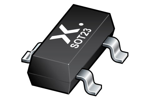
A BAV70 diode is housed in a small three-legged body. On one side is a single leg, the common cathode. On the other side are a pair of legs, the anodes. Effectively, a BAV70 operates like two diodes combined together.
You will probably need a good pair of metal tweezers to attach the diodes. I also recommend having a flux pen. Head-mounted magnifying glasses are also nice to have (like this model from Kinetic Labs), but they aren’t required.
Find a BAV70 footprint on the PCB.
If you want to use flux, apply a little on each of the three pads of the footprint.
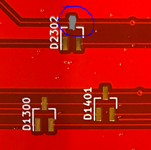
Melt solder onto the cathode pad of the footprint (the one by itself).
a.k.a. “tinning the pad”
Line up the diode with tweezers so that its three legs match all three pads.
The cathode pin of the diode will initially sit on top of the cooled solder on the pad.
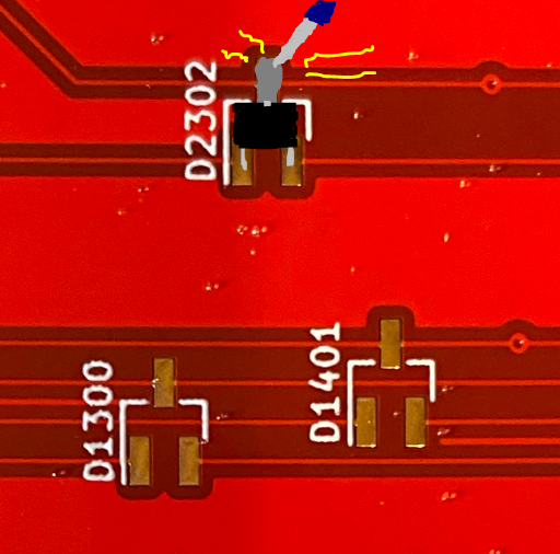
Reflow (melt) the solder underneath the cathode.
The cathode pin should drop into place.
While the solder is melted, this is a good time to use tweezers to adjust the diode position so that the other two legs stay aligned.
Remove the soldering iron. After the solder cools, the diode should now be firmly in position.
Tin the other two pads, connecting to each of the anode legs.
Once you get the hang of the process, I recommend performing these steps in an assembly line process. I tend to do this in groups of 6-8 diodes at a time, tinning all the cathode pads, lining up the diodes, reflowing the cathodes, then soldering the remaining legs.
Soldering the Elite C
The Elite C must be attached to the Red or Blue PCB in order to provide its MCU and USB receptacle. Be sure to attach it to the underside of the board with the components of the Elite C facing out, away from the PCB. If surface-mounting, this means the Elite C will lay flat on the PCB.
Surface-Mounting the Elite C (Recommended)
While this process requires a little patience, it will reduce the number of points-of-failure possible for the board and keeps all soldering on the underside of the PCB.
Fully surface-mounted Elite C. Note that this is a PCB from the 2021 batch (version 1); the second generation lacks the SW1 footprint.
Position the Elite C.
The flat underside of the Elite C should lay flush on the bottom of the PCB.
The grooves of the castellated pins should match the pads on the PCB.
Use some electrical tape or similar to hold the Elite C in position.
I used the through-hole standoffs temporarily for this purpose, being sure to remove them to avoid accidentally soldering them in position.
The edges of the pads on the Elite C are “castellated” and have metal running all the way down the side. Your goal is to get the solder to connect the Elite C’s pads to the PCB’s flat pads.
Start by heating a single PCB pad on one of the corners. Then melt a little solder to it (tin the pad).
Preferably, don’t start with GND pins, as they may require higher soldering temperatures (since the grounded PCB will dissipate the heat more).
Once the tin is on the pad, double check the alignment of your Elite C.
Place your iron such that it heats the flat pad of the PCB, the corresponding pad of the Elite C, and the solder from step 4.
The solder should stick to both pads, making a sort of angled bridge between them.
You may need more solder for this, and that’s okay.
Remove the iron. Check the positioning of your Elite C. If everything is still lined up, solder the remaining corner pins.
Once you have a couple of the castellated pads soldered to the PCB correctly, you probably don’t need the tape or any other anchors from step 2 any more.
Solder all the pads, one by one. Applying a little flux to the pads beforehand can be helpful too.
If you make a “bridge” between pads, as seen in the picture below, desolder and redo those pads.
Example of a mistakenly bridged pair of pins.
Through-Hole Soldering the Elite C
This guide won’t go into the details here, but attaching the Elite C in a through-hole manner is straightforward.
Solder the three standoffs to the Elite C so that the long ends of the standoff pins are pointing to the opposite side of the components.
To keep the standoffs straight, some recommend attaching them to the Elite C using a breadboard or similar.
Solder the long ends of the standoffs to the underside of the PCB.
Incorrect leg alignment, with legs and components facing the same direction.Correct leg alignment with components facing away from legs. Ignore the fact that this image is of a Pro Micro, which is not compatible with Jabberwocky. Be sure to solder all three standoffs, not just the two sides seen above.
Socketing the Elite C
You can modify the instructions for through-hole soldering the Elite C to use pin sockets instead. I don’t have a lot of good experience with these, and personally I don’t think the extra labor is actually worth it.
Installing the Caps & Num Lock Indicator LEDs
If you wish to use the optional LEDs for caps and num lock indicators, you will need to solder both the resistors and the LEDs themselves to the board.
Soldering Resistors
It is recommended, but not required, that the resistors are soldered to the PCB before adding switches.
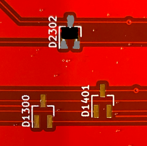
Resistor footprint, as seen in KiCad 3D viewer. Look for these near the standard positions for Caps Lock and Num Lock.
Locate the resistor pads near the Caps & Num Lock switches.
The resistors use a hybrid footprint, with two surface-mount pads and two through-hole pads immediately adjacent.
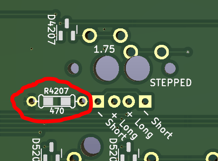
The Jabberwocky kits come with resistors for surface-mounting. If you lose these or find them too difficult to solder, you can just mount standard 470 ohm through-hole resistors instead.
Tin one of the two pads (melt solder on it).
Carefully place the resistor on top of the footprint so that one leg is on each pad, with one leg sitting on top of the solder you just added.
Unlike a diode, the orientation of the resistor doesn’t matter, just so long as the legs are flush with the PCB.
Reflow (melt) the solder, letting the leg of the resistor drop to the surface of the PCB.
If the resistor becomes misaligned, use tweezers to gently push it back into correct position while the solder is melted.
Remove the soldering iron, letting the solder harden around the leg.
Tin the other pad to the other leg.
Compatible Switches for LEDs
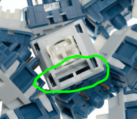
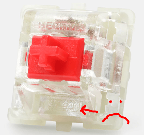
Through-hole in-switch LEDs have become less common in the hobby, and many switches don’t support them. If you want to use the indicators, you’ll need at least two switches that do support them. Look for two narrow rectangular slots in the plastic on the edge of the switch that’s opposite its metal pins.
Example of a switch that DOES support in-switch LEDs, courtesy of CannonKeys.This Cherry switch from Drop lacks the slots needed for through-hole LED support.
Installing In-Switch LEDs
Unlike other components of the Red or Blue PCBs, this step must occur after the switches (and switchplate) are attached to the PCB (or at least the caps and num lock switches).
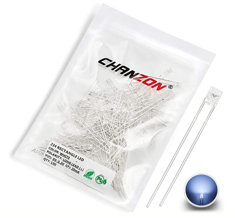
In your kit you should have two Chanzon through-hole LEDs. They should shine either white or yellow; feel free to replace these with your own compatible LEDs if you prefer a different color.
LED stands for “light-emitting diode,” and as with any diode, its orientation matters. For this Chanzon model, the anode is the longer leg, and the cathode is the shorter leg.
Thread the two legs of the diode through the slots of the corresponding switch, leaving the bulb on top of the switch housing.
The legs should thread through the PCB as well, with the longer leg (anode) coming through a circular pad and the shorter leg (cathode) through a square pad.
For the Caps Lock indicator, there are two adjacent pairs of pads (one for a full caps lock, one for stepped).
Pay attention to the orientation of the legs, as it differs for each type of caps lock key.
Solder the legs of the LED to each through-hole pad.
Clip the excess wire from the LED legs.
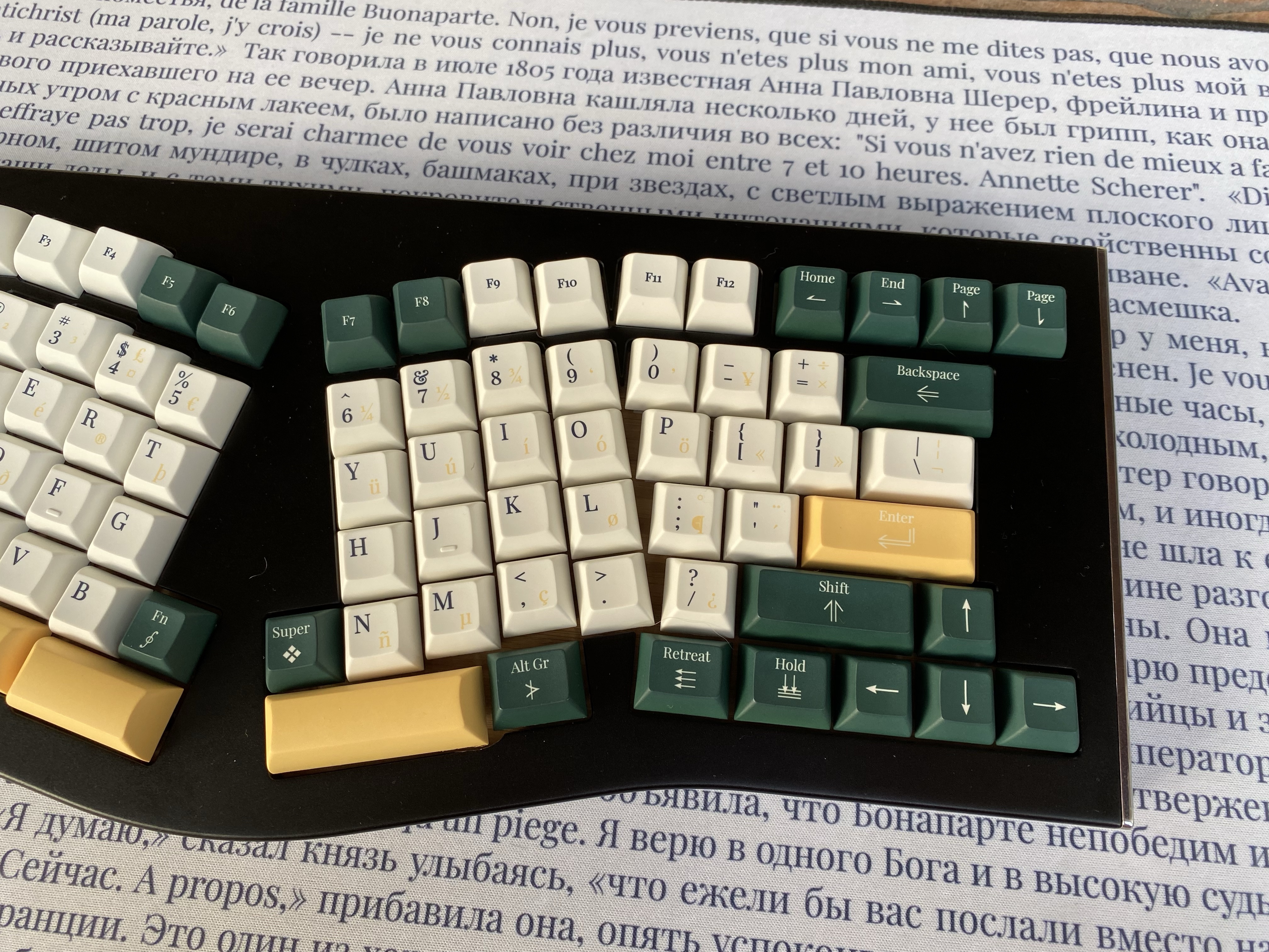
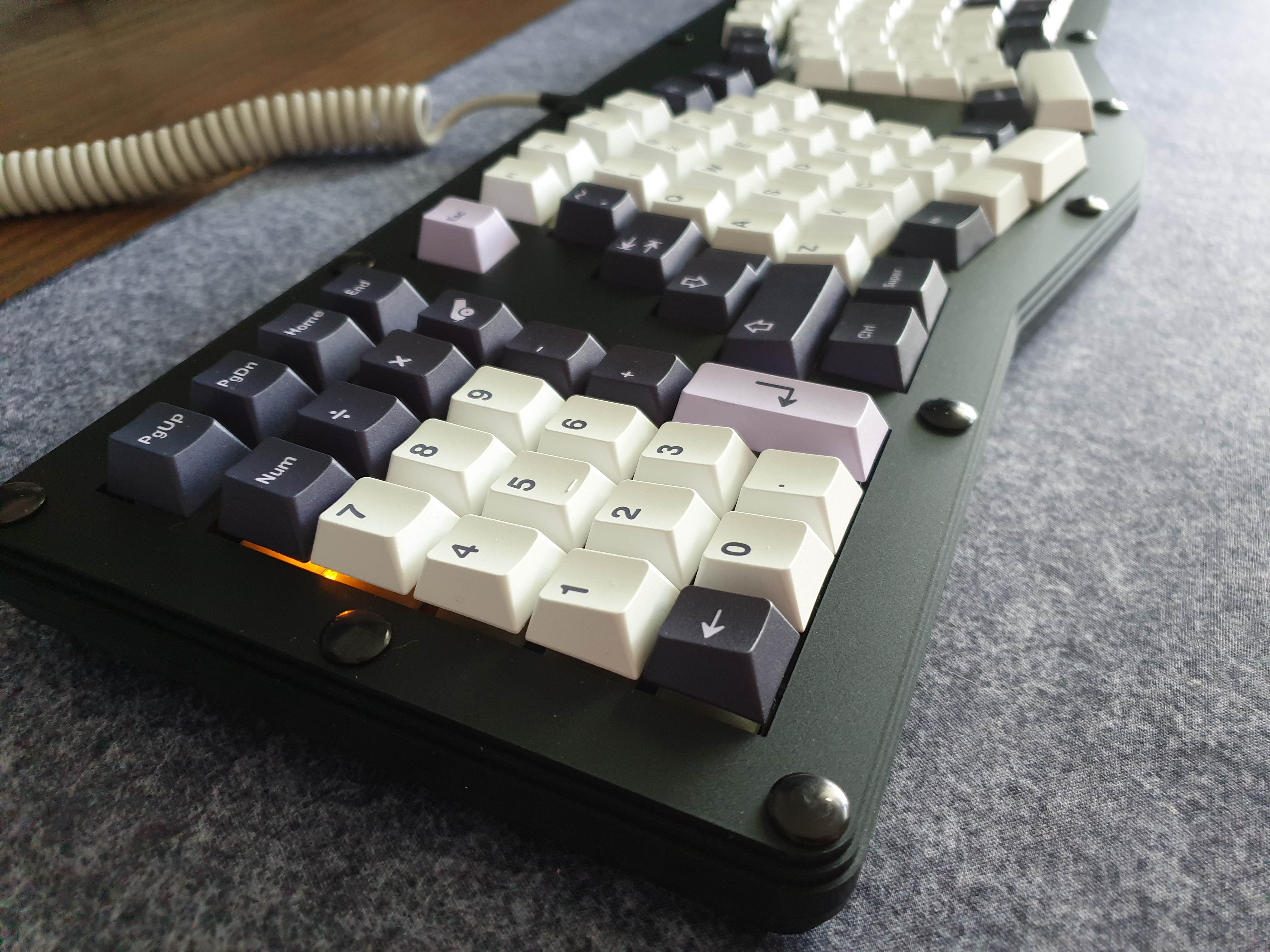
Example Dexterous FR4 build (v1) with in-switch Num Lock indicator. Lens keys make these show up the best but are not strictly required, as the light tends to be visible coming from below the keycap.
The Jabberwocky keyboard, which comes in a variety of case and PCB options, is now available to order! DIY kits are in-stock, and I’m taking reservations for the fancy-shmancy CNC version pictured above. Head on over to the full description & order page for more information!
It is with a heavy heart that I have to announce that the Group Buy for GMK Prussian Blue has been canceled. The sales have not been strong enough to justify moving forward.
I hope this is not the last we will see of the project. It may be that at a later date, GMK’s pricing and lead times will no longer be a source of mockery among the community. Or it may be that this set will have new life under a different profile. I am unsure.
I just know that it has a real shot at being a successful project, but that this isn’t its moment.
Pricing for other vendors & locales is still being worked out but should be comparable to these. Mark you calendars!
Update 31 May 2022
We have received an updated quote from GMK for the International Kit and are revising pricing accordingly. MOQ for that kit is being decreased from 100 to 50.
After a very long wait, Keyreative is finally at the stage where they’re starting to produce samples of the KAT Napoleonic kits. Color-matching was completed several months back, so the focus now is on overall cap shape / quality, dyesub accuracy, and kit content accuracy. These are the first samples I received post color-matching, and overall I feel like we’re progressing toward a good deliverable product.
These samples consisted of one alpha kit and some assorted mods. It was enough to fill a 60%.
The color quality is great, even on the reverse dyesub keys.
The reverse dyesub keys seem to be a tiny bit shorter than their counterparts.
This is a bit more noticeable for the 1u keys.
The “walls” of the larger mod keys also seem to shrink a bit for reverse dyesub caps, making them just a tiny bit smaller than the alpha keys proportionally.
There are a number of legend alignment issues that I’ve already been in conversation with Keyreative about.
As part of promoting DSS Late Harvest, I’m giving away one of the last remaining Jabberwocky keyboard prototypes! Details can be found on my Reddit post. Upvotes are always appreciated.
Group Buy preorders for DSS Late Harvest end on May 19th. All plastic kits will be made. Estimated delivery is October 2021.