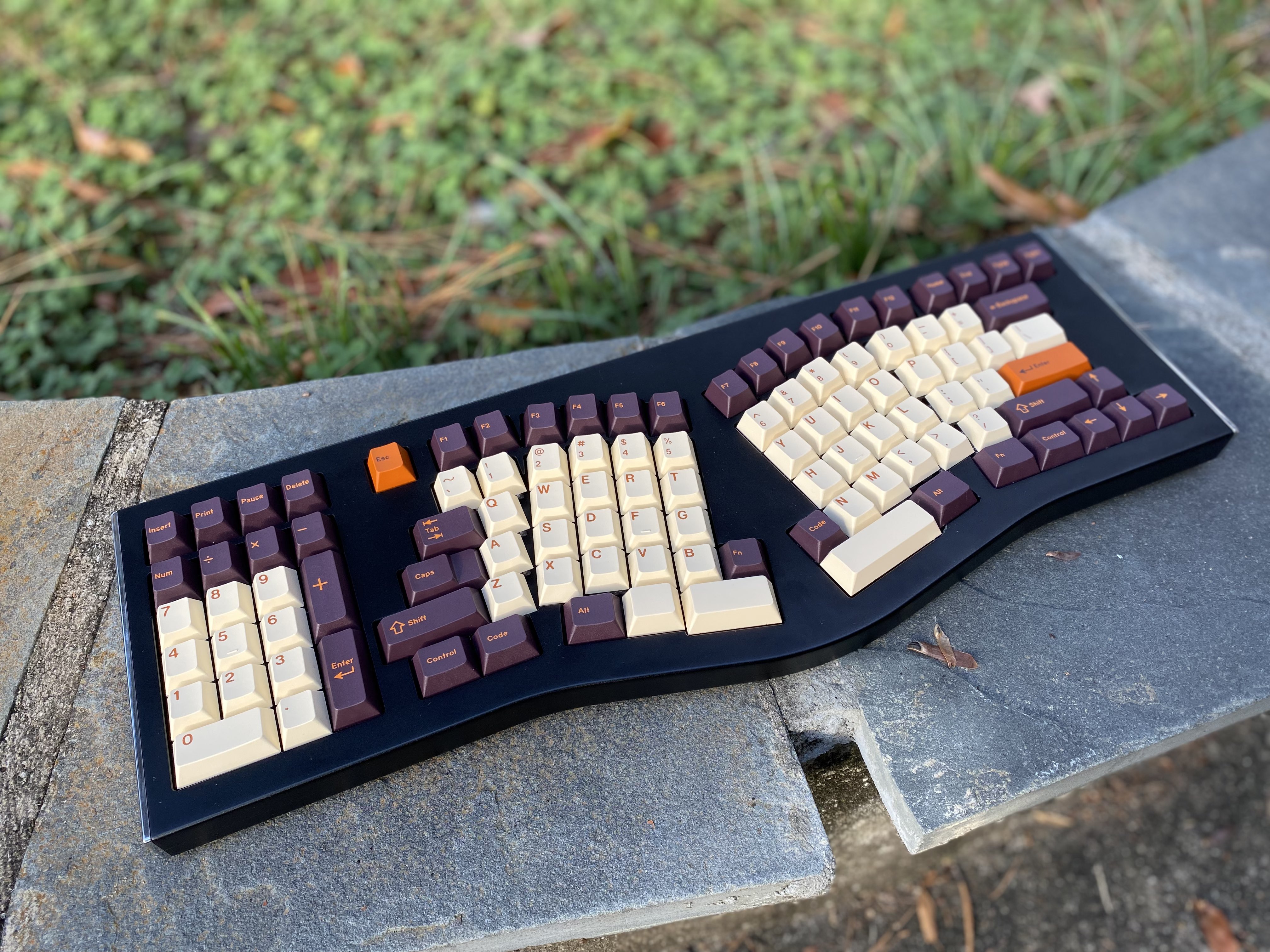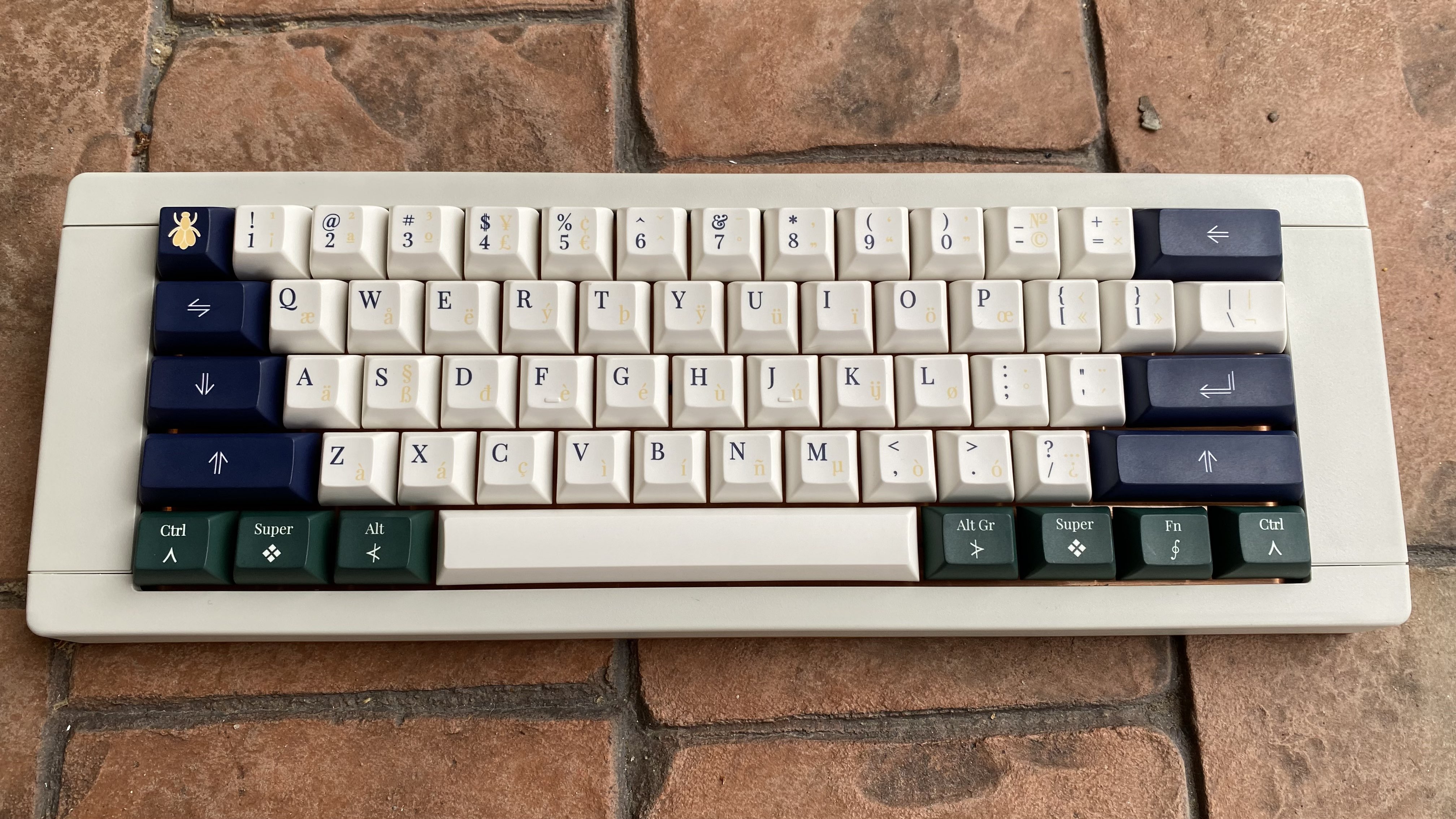
This guide includes some basic steps for attaching necessary components to the two DIY Jabberwocky PCBs together (red for dexterous, blue for sinister).
These instructions will cover the soldering of components excluding switches. I highly recommend soldering the diodes, Elite C, and resistors before soldering switches.
These materials come with the red / blue kit:
- Required:
- The PCB itself
- 57x BAV70 diodes (in a black plastic strip)
- Elite C
- Optional, used for Caps & Num lock indicators:
- 2x resistors (in a very small white paper strip)
- 2x in-switch through-hole LEDs
Soldering the Diodes

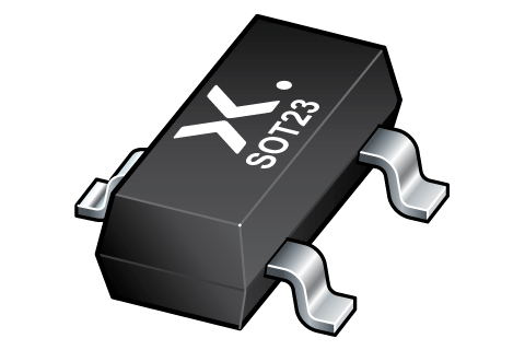
A BAV70 diode is housed in a small three-legged body. On one side is a single leg, the common cathode. On the other side are a pair of legs, the anodes. Effectively, a BAV70 operates like two diodes combined together.
You will probably need a good pair of metal tweezers to attach the diodes. I also recommend having a flux pen. Head-mounted magnifying glasses are also nice to have (like this model from Kinetic Labs), but they aren’t required.
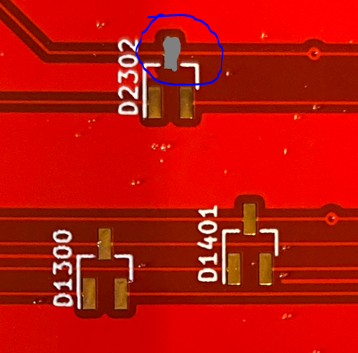
- Find a BAV70 footprint on the PCB.
- If you want to use flux, apply a little on each of the three pads of the footprint.
- Melt solder onto the cathode pad of the footprint (the one by itself).
- a.k.a. “tinning the pad”
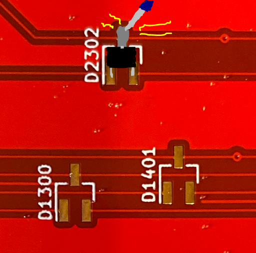
- Line up the diode with tweezers so that its three legs match all three pads.
- The cathode pin of the diode will initially sit on top of the cooled solder on the pad.
- Reflow (melt) the solder underneath the cathode.
- The cathode pin should drop into place.
- While the solder is melted, this is a good time to use tweezers to adjust the diode position so that the other two legs stay aligned.
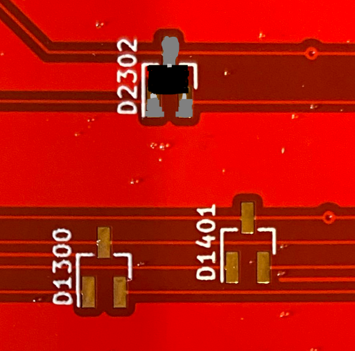
- Remove the soldering iron. After the solder cools, the diode should now be firmly in position.
- Tin the other two pads, connecting to each of the anode legs.
Once you get the hang of the process, I recommend performing these steps in an assembly line process. I tend to do this in groups of 6-8 diodes at a time, tinning all the cathode pads, lining up the diodes, reflowing the cathodes, then soldering the remaining legs.


Soldering the Elite C
The Elite C must be attached to the Red or Blue PCB in order to provide its MCU and USB receptacle. Be sure to attach it to the underside of the board with the components of the Elite C facing out, away from the PCB. If surface-mounting, this means the Elite C will lay flat on the PCB.
Surface-Mounting the Elite C (Recommended)
While this process requires a little patience, it will reduce the number of points-of-failure possible for the board and keeps all soldering on the underside of the PCB.

- Position the Elite C.
- The flat underside of the Elite C should lay flush on the bottom of the PCB.
- The grooves of the castellated pins should match the pads on the PCB.
- Use some electrical tape or similar to hold the Elite C in position.
- I used the through-hole standoffs temporarily for this purpose, being sure to remove them to avoid accidentally soldering them in position.
- The edges of the pads on the Elite C are “castellated” and have metal running all the way down the side. Your goal is to get the solder to connect the Elite C’s pads to the PCB’s flat pads.
- Start by heating a single PCB pad on one of the corners. Then melt a little solder to it (tin the pad).
- Preferably, don’t start with GND pins, as they may require higher soldering temperatures (since the grounded PCB will dissipate the heat more).
- Once the tin is on the pad, double check the alignment of your Elite C.
- Place your iron such that it heats the flat pad of the PCB, the corresponding pad of the Elite C, and the solder from step 4.
- The solder should stick to both pads, making a sort of angled bridge between them.
- You may need more solder for this, and that’s okay.
- Remove the iron. Check the positioning of your Elite C. If everything is still lined up, solder the remaining corner pins.
- Once you have a couple of the castellated pads soldered to the PCB correctly, you probably don’t need the tape or any other anchors from step 2 any more.
- Solder all the pads, one by one. Applying a little flux to the pads beforehand can be helpful too.
- If you make a “bridge” between pads, as seen in the picture below, desolder and redo those pads.

Through-Hole Soldering the Elite C
This guide won’t go into the details here, but attaching the Elite C in a through-hole manner is straightforward.
- Solder the three standoffs to the Elite C so that the long ends of the standoff pins are pointing to the opposite side of the components.
- To keep the standoffs straight, some recommend attaching them to the Elite C using a breadboard or similar.
- Solder the long ends of the standoffs to the underside of the PCB.


Socketing the Elite C
You can modify the instructions for through-hole soldering the Elite C to use pin sockets instead. I don’t have a lot of good experience with these, and personally I don’t think the extra labor is actually worth it.
Installing the Caps & Num Lock Indicator LEDs
If you wish to use the optional LEDs for caps and num lock indicators, you will need to solder both the resistors and the LEDs themselves to the board.
Soldering Resistors
It is recommended, but not required, that the resistors are soldered to the PCB before adding switches.
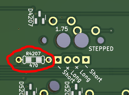
- Locate the resistor pads near the Caps & Num Lock switches.
- The resistors use a hybrid footprint, with two surface-mount pads and two through-hole pads immediately adjacent.
- The Jabberwocky kits come with resistors for surface-mounting. If you lose these or find them too difficult to solder, you can just mount standard 470 ohm through-hole resistors instead.
- Tin one of the two pads (melt solder on it).
- Carefully place the resistor on top of the footprint so that one leg is on each pad, with one leg sitting on top of the solder you just added.
- Unlike a diode, the orientation of the resistor doesn’t matter, just so long as the legs are flush with the PCB.
- Reflow (melt) the solder, letting the leg of the resistor drop to the surface of the PCB.
- If the resistor becomes misaligned, use tweezers to gently push it back into correct position while the solder is melted.
- Remove the soldering iron, letting the solder harden around the leg.
- Tin the other pad to the other leg.
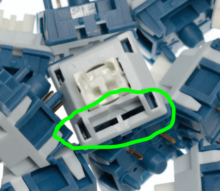
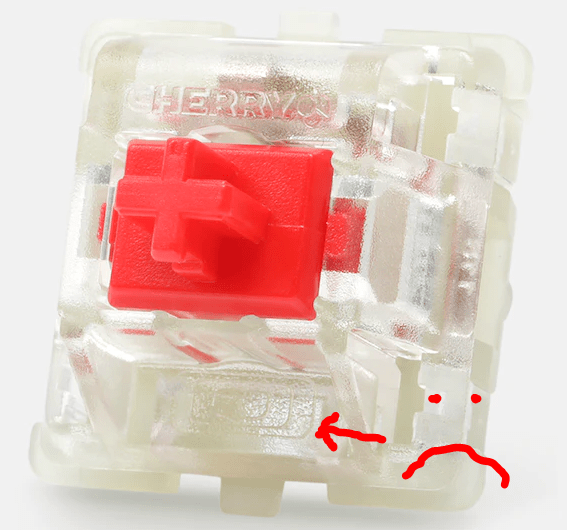
Compatible Switches for LEDs
Through-hole in-switch LEDs have become less common in the hobby, and many switches don’t support them. If you want to use the indicators, you’ll need at least two switches that do support them. Look for two narrow rectangular slots in the plastic on the edge of the switch that’s opposite its metal pins.
Installing In-Switch LEDs
Unlike other components of the Red or Blue PCBs, this step must occur after the switches (and switchplate) are attached to the PCB (or at least the caps and num lock switches).
In your kit you should have two Chanzon through-hole LEDs. They should shine either white or yellow; feel free to replace these with your own compatible LEDs if you prefer a different color.
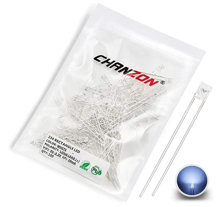
LED stands for “light-emitting diode,” and as with any diode, its orientation matters. For this Chanzon model, the anode is the longer leg, and the cathode is the shorter leg.
- Thread the two legs of the diode through the slots of the corresponding switch, leaving the bulb on top of the switch housing.
- The legs should thread through the PCB as well, with the longer leg (anode) coming through a circular pad and the shorter leg (cathode) through a square pad.
- For the Caps Lock indicator, there are two adjacent pairs of pads (one for a full caps lock, one for stepped).
- Pay attention to the orientation of the legs, as it differs for each type of caps lock key.
- Solder the legs of the LED to each through-hole pad.
- Clip the excess wire from the LED legs.